

How To Install A Body Kit
How to Install Rough State two" Trunk Elevator Kit on your 1997-2006 Wrangler
Tools Required
- Floor jacks
- Woods Blocks
- Cycle chocks
- Torque wrench
- i/2 drive ratchet
- five/8" socket/wrench
- 3/four" socket /wrench
- Safety spectacles
- Thread locker
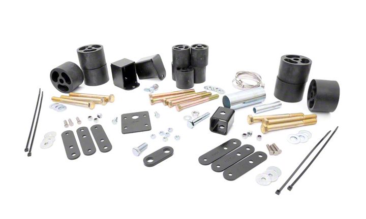
Shop Parts in this Guide
- Rough Country two-Inch Torso Lift Kit (97-06 Jeep Wrangler TJ)
- Rough Country 3-Inch Body Lift Kit (97-06 Jeep Wrangler TJ)
Congratulations on your purchase of a new Rough Country ii"/3" Body Lift. Nosotros are committed to providing you with the all-time product available for the all-time value. Your satisfaction is our highest priority! This instruction sheet addresses both two" and 3" body lifts for Jeep TJ
Rough Country recommends a certified technician installs this organisation. In addition to these instructions, professional person knowledge of detach/reassembly procedures as well as mail installation checks must exist known. Check the kit hardware confronting the parts list. Be sure you have all the needed parts and empathise where they go. As well please review the tools needed listing and make sure you have needed tools.
Product USE Data
As a general rule, the taller a vehicle is the easier it will roll. We strongly recommend, because of rollover possibility, that the vehicle exist equipped with a functional roll-bar and cage arrangement. Seat belts and shoulder harnesses should be worn at all times. Avoid situations where a side rollover may occur.
Do not add, alter, or fabricate whatever factory or later-market parts which increase vehicle acme over the intended height of the Rough Country production purchased. We will not be responsible for any product that is altered.
This 2"or 3" combination body lift / replacement trunk bushing kit can exist used with Rough Country's lift kit if desired to allow the fitment of larger tires for off route use.
Observe TO DEALER AND VECHICLE OWNER
Any vehicle equipped with whatever Crude Country product must take the "Warning to Driver" decal installed on the sun visor or nuance. The decal is to act as a constant reminder for whoever is operating the vehicle of its unique handling characteristics.
BODY LIFT PRE INSTALLATION NOTES:
To ensure the SRS system (Air handbag system) is not accidentally deployed during installation, e'er basis yourself and the vehicle. Exercise farthermost caution when working nearly SRS sensors and wiring. Exercise not allow anyone near air bags during the elevator kit installation. Accidental deployment tin can upshot in serious injury or death. As a precaution, the negative and positive wire should exist disconnected from the battery with the negative wire being removed kickoff. Also the air bag fuse can be removed from the fuse panel backside the glove box. Cheque hoses and wiring before and recheck during installation taking caution to not overextend them.
INSTALLATION INSTRUCTIONS
1. Disconnect negative battery cable using 13mm wrench. See Photograph one.
2. Open up glove box and remove strap from glove box door. Put door out of way. remove both 10 amp airbag fuses. See owners manual. See Photo 2.
3. Remove plastic jeep sway-bar cover using 10mm socket. Run into Photograph three.
iv. If equipped with fog light on the bumper remove push pivot from fender and unplug light.
5. Remove air intake hose from air filter housing and throttle torso using a screwdriver. See Photo 4.
6. Remove coolant overflow hose and bottle from fan shroud and radiator. See Photo 5.
7. Remove the four basics from radiator fan then remove the 4 bolts holding fan shroud to the radiator using a 11mm socket. See Photo half-dozen. Do non drop or allow the fan rest again the radiator every bit this may cause damage to the cooling fins.
viii. Remove clip holding transmission line to shroud. Remove both shroud and fan from vehicle.
nine. Remove the six bolts from radiator using 10mm socket. Encounter Photo seven.
x. Unplug vacuum hose from brake booster. See Photo 8.
11. Remove heater hoses from clip on side of valve encompass. See Photo 9.
12. Unplug or unclip the blackness and greyness wiring harness connectors and any other harness present in this location. Meet Photo 10.
13. On driver side front fender well remove the clips from gap guard. See Photograph 11.
xiv. Then using a 15mm wrench remove the two bolts on steering carrier bearing subclass. See Photo 12.
xv. Remove gas cap. Remove the iv screws from fuel filler assembly. See Photo xiii.
sixteen. Remove the screws for fuel filler bezel. See Photo 14.
17. Depending on the year of jeep if your EVAP canister or ( charcoal canister ) is under hood on drivers fender skip to footstep 23.
18. If the EVAP canister is located on the passenger side rear cycle well, proceed with step 19.
19. Remove cycle from passenger rear using a 19mm socket then remove the 7 push clips from inner fender well. Meet Photo 15.
20. Remove fender well. See Photo 16.
21. Using a 13mm socket, remove EVAP canister plate. Come across Photograph 17.
22. Unclip the black clench around hose just above the white connector. See Photograph eighteen.
23. Automatic trans only!!!!!!! 97-02 Pictured. Remove the six bolt on console one is in cup holder, 2 are in console compartment every bit shown in Photograph xix. Move passenger seat forward and two bolts are on the side of console. Last bolt is under shift indicator as shown in Photograph 20. All bolts are 10mm.
24. Raise panel upwardly enough to pull carpet out on driver side to gain admission to the 4 bolts holding the 4wd shifter lever pin bracket to the body using a 10mm wrench. See Photo 21.
25. Loosen but do not remove the xi body bolts using a 16mm socket. One bolt is under radiator support, iii bolts are under both doors, two are over rear axle and 2 are at each rear corner. Encounter Diagram 1 on first page.
26. On passenger side remove torso bolts and front body commodities. Using a jack stand or floor jack and a slice of wood slowly raise body off of frame. Enhance body only high plenty to become body puck in between the body and stock trunk bushing every bit shown in Photograph 23. Go along to the contrary side and install the torso pucks. Secure using the half-dozen supplied 1/2" bolts on body mounts nether both doors.
27. Use the supplied 7/16" bolts on torso mounts over the axle, at both rear corner and front radiator support.
28. Place the included grill support bracket equally shown under the stock rubber back up. Mark and drill every bit shown in Photograph 24 using a 9/32" drill flake. Secure the bracket to the frame using the supplied 5/16" self tapping bolts. Practise not overtighten the self tapping bolts.
29. Remove nix tie from around axle vent tube and fuel filler vent hose. See Photo 25. Film looking through the gas filler housing.
30. In between torso and frame on drivers side, near gas tank remove footing strap from frame. See Photograph 26.
31. Using a 1/4 inch socket remove both clamps effectually fuel filler hoses at gas tank. See Photograph 27.
32. Remove the filler hoses. Encounter Photo 28.
33. With the fuel filler hoses out, cut the hoses in a straight spot and insert the 1-one/2" x 4" and iii/4" x 4" extensions into filler hoses. Utilise the supplied clamps and tighten using a 8mm socket. See Photograph 29.
34. Reinstall extended fuel filler hoses onto gas tank with the mill hardware. Tighten stock clamps with 1/4 socket.
35. Reinstall basis strap and null tie axle vent tube back to fuel filler vent hose.
36. Reinstall fuel filler assembly to bezel and bezel dorsum to the trunk.
37. On the EVAP canister, if located in the rear passenger side fender bicycle, Slide the blackness clamp up to the hose about ii inches and reattach to body. Reinstall EVAP canister embrace plate using 13mm. Install fender well if removed.
38. Remove 4wd pivot bracket from under vehicle on driver side near transmission that was loosened in step 24. Encounter Photo 31.
39. Using a 10mm socket remove the pivot begetting from subclass and install into the new relocation subclass using the supplied bolts ane/iv" 10 3/4" bolts and nuts. Tighten using a 11mm wrench. See Photograph 32.
xl. Reinstall assembly back onto vehicle with the factory hardware. Tighten using a 10mm wrench.
41. Install the supplied i-1/2" ten ane-1/2" ten 1-3/four" long inch square tubing onto steering carrier bearing using the supplied 10mm x 60mm bolt and washer. See Photo 33.
42. Install the side steering carrier begetting strap using the stock commodities on lesser and the supplied 7/16" 10 ane" commodities, washer and nut on top. Come across Photo 34. Utilise a 17mm wrench to tighten 10mm bolt ,16mm and 17mm for new 7/16" commodities and 15mm for stock bolt.
43. Reinstall gap guard. Note: Make certain fuel lines are abroad from steering carrier bearing.
44. Reconnect front factory fog light if equipped.
45. Zip tie the blackness and grayness connectors under hood at firewall.
46. Reconnect vacuum hose to brake booster and reattach heater hose to clips.
47. Install supplied 1/4" stud into supplied radiator drop brackets using a small socket and hammer. Making certain the stud is secure to preclude spinning. See Photo 35.
48. Install one/4 nuts onto studs and tighten using 11mm wrench. This nut is beingness used every bit a spacer to allow the radiator flange to sit flush. See Photo 36.
49. Install the six radiator drop subclass using stock bolts. Brand sure you lot install into right pigsty in drop bracket for 2 inch torso lift. The middle pigsty is for the 2" body lift. Make certain brackets are straight before tightening.
fifty. Install radiator onto brackets making sure A/C lines clear on the lesser of the radiator. Trim if necessary.
51. Using the supplied 1/four" nuts and tighten radiator to drop brackets using 11mm socket.
52. Install axle vent hose onto the peak radiator stud.
53. Reinstall fan and radiator shroud with stock bolts using a 10 mm socket on shroud and 13mm for fan.
54. Reinstall coolant overflow canteen and hose.
55. Reinstall intake hose to air filter hosing and to throttle torso.
56. Reinstall prune on trans line to fan shroud.
57. Reinstall plastic jeep cover over sway-bar using stock bolts.
58. Install airbag fuses dorsum into fuse box and install glove box.
59. Reconnect bombardment cables using 13mm wrench.
60. Recheck all fasteners, lines, wiring and hoses.
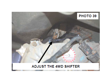
61. Make certain 4wd shifts smoothly. Adjust 4wd shifter under vehicle using 13mm wrench. See Photo 39. Check steering make sure there is no bounden.
97-02 MANUAL SHIFTER INSTALLATION INSTRUCTIONS
1. To install the Manual shifter bracket remove the 4 bolt property the lower shifter boot in place using a 7mm socket. Come across Photograph 1.
2. Then remove shifter from trans by pulling upwardly and you may have to employ a hammer. See Photo two.
3. Install new shifter extension until information technology bottom out. Tighten the supplied allen screws using a 3mm allen wrench. Come across Photo 3.
4. Install shifter onto shifter extension making sure it is pressed on all the way. See Photo iv.
five. Cheque shifter performance. Make certain there is complete engagement in all gears and that at that place is no interference with floor pan.
6. Reinstall lower shifter boot using 7mm socket.
7. Install console using stock hardware and 10mm socket. Install upper shifter boot and loving cup holder.
8. Check shifter for interference.
1. Remove shifter kick and loving cup holder from console. See Photograph one & 2.
2. Using a 10mm socket remove the bolts from panel every bit shown in Photo 3 & 4. I is in cup holder other is nether shifter kicking.
iii. Remove console. If equipped unplug airbag switch.
4. Using a 45mm torx head socket remove shifter. See Photo 5.
5. Install new shifter extension using stock bolt and supplied 1/4" allen screw. See Photo half-dozen. Tighten using a 45mm torx bit and a 1/8 allen wrench.
half-dozen. Reinstall shifter boot on shifter if removed.
7. Reinstall shifter on new extension with new 5/16" x1"commodities, using a 1/4" allen head to tighten.
eight. Using a 10mm socket reinstall console with stock bolts.
1. When installing a iii" trunk lift these steps will exist performed to ensure the 4wd shifter engages in all ranges of the transfer example.
2. Remove 4wd shifter rod nether vehicle using a screwdriver or pair of pliers. Meet Photograph one & 2.
3. Mark a straight three inch long line on the thicker office of shifter rod. See Photo 3.
4. Using a grinder brand a apartment surface beside the line. Meet Photo iv.
v. Cut the linkage ane inch from the taper role on rod. See Photo 5.
6. Clean the cut area then install new extension sleeve onto linkage until it bottoms out. Encounter Photo 6.
vii. Tighten 1/4" allen screws using i/8" allen wrench onto the grinded apartment area.
viii. Reinstall shifter rod back onto vehicle and conform for proper performance.

Source: https://www.extremeterrain.com/rough-country-2-body-lift-kit-tj-rc605-manu-install.html
Posted by: smithcomraced.blogspot.com
0 Response to "How To Install A Body Kit"
Post a Comment